Annotation: Telecommunications laboratory (telco lab) is the next step in the old hardware collection’s further usage and analysis. About 10+ various [mainly U.S.Robotics (USR) branded] voice 56kbit (fax)modems for dial-up Internet connection had been collected. This article gives a Prove of Concept (PoC) to the modem-modem link establishment over the VoIP RTP stream with aim to build a dial-in ISP service. Various VoIP technology’s underlying parameters, and modem configurations had been tuned with batch dial-up connection testing being executed, and then commented. Tests were performed with the usage of remote SIP operator’s circuit, and local PBX SIP circuit.
ŠARA, Kryštof. “Dial-up over VoIP service ISP.” Krusty’s Space, Jan 14, 2024, https://krusty.space/projects/dialup_over_voip/.
introduction
This article gives a verbose introduction to the dial-up modem-related paradigm, its problems, and practical usage. Next section provides used hardware and software configuration settings examples. Various modem’s outputs are present and commented there too. In the end, a batch modem-to-modem connection testing is executed while numerous parameters being tuned and scraped. Basic GNU/Linux shell knowledge is required as well as some understanding of the VoIP technology.
The main inspiration source could be seen in the Doge Microsystems blog post [4] about making the dial-up/dial-in ISP (Internet Service Provider) over VoIP (Voice over IP).
interconnection idea
For faxmodem feasible operation, a working telephone circuit/loop is required side by side with a compatible serial port having terminal. PSTN (Public Switched Telephone Network) is being emulated using (mainly) software PBXs (Private Branch eXchange) supporting SIP (Session Initiation Protocol) and VoIP RTP (Real-time Transport Protocol) packet flow. For the classic telephone cables (RJ11 6P2C/6P4C) being used by modems, an independent VoIP SIP hardware gateway with analogue FXS (Foreign eXchange Station) ports for POTS (Plain Old Telephone System) devices is deployed too in the networking. [2] [3]
The target dial-in server consists of:
- a software PBX (local circuit),
- a PPP (Point-to-Point Protocol) link daemon with PAP authentication,
- an IPTables-powered GNU/Linux kernel packet router/forwarder.
The server is connected to the Internet (upstream ISP) using a basic coaxial cable modem CPE (Customer Premises Equipment). A voice faxmodem pool for multiple concurrent client dials is connected to the server using serial-to-USB adapters and cables.
As the basic telephone call bandwidth (0,3–3,4 kHz) is used, the supporting VoIP RTP stream has to be established and stable for the whole time. This stream (with its signalling too) is carried (mostly) between the VoIP SIP gateway and some SIP server as a normal IP Internet traffic. [2] [46]
As soon as the telephone circuit is ready for a reqular voice call, the faxmodems are ready for the dialing. The server’s modem(s) acts like an answering modem, the client’s modem is used as a dialing modem. During the initial part of the call, modems are analyzing the call quality, interchanging supported protocols, and negotiating possible connection speeds. When a handshake by modems is made, a PAP authentication takes place. After a successful access to the server, a PPP link is established. This link is then used for various diagnostic tests described further. Also, this link can be used by a customer/client to access the Internet.
Simplified interconnection schemes are shown and commented in Figg. 1 and 2 (see more below).
remote provider circuit
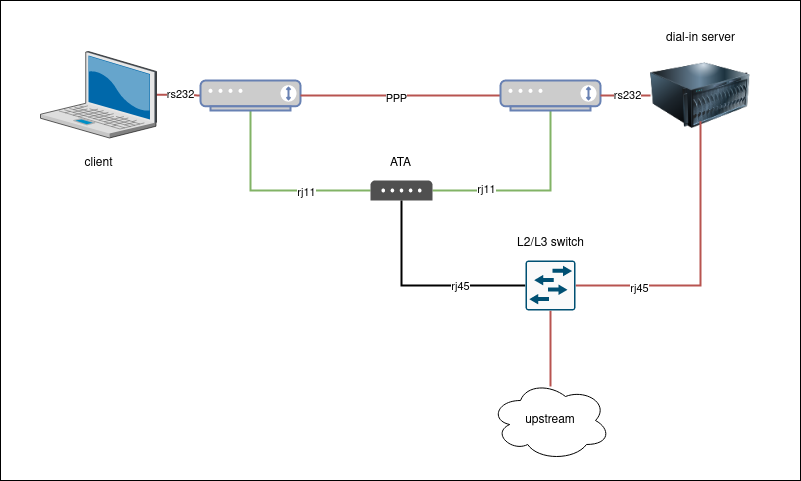
In the first case, the SIP server is located at the remote operator/provider’s network with the corresponding remote PBX. A client (and client’s modem) uses PSTN and POTS socket to dial the dial-in server’s modem.
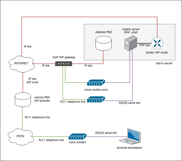 Fig. 1:
Hardware and software lab parts interconnection scheme showing the local labolatory setup, local and remote SIP servers/PBXs used by the lab’s VoIP gateway, and a client (terminal workstation) connected to the server’s modem via PSTN and remote telephone company SIP trunk — Odorik.cz VoIP operator providing the public telephone number for the server’s dial-in modem.
Fig. 1:
Hardware and software lab parts interconnection scheme showing the local labolatory setup, local and remote SIP servers/PBXs used by the lab’s VoIP gateway, and a client (terminal workstation) connected to the server’s modem via PSTN and remote telephone company SIP trunk — Odorik.cz VoIP operator providing the public telephone number for the server’s dial-in modem.
local lab circuit
In the second case, the SIP server is located locally, as a part of the dial-in server software equipment. Thus the labolatory’s VoIP SIP gateway is connected directly to the dial-in server’s SIP service. The client’s modem uses FXS port of the same VoIP SIP gateway.
Note: the client’s modem using the same VoIP SIP gateway model can be used for dialing using the remote SIP server too.

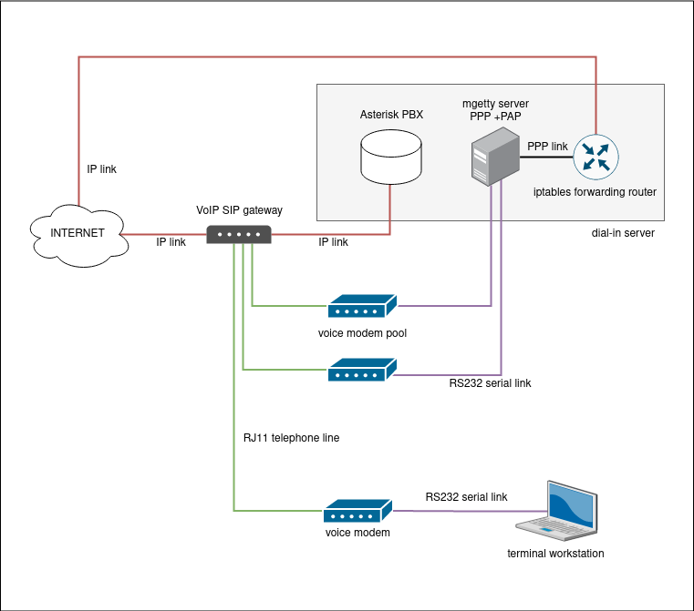 Fig. 2: Hardware and software lab parts interconnection scheme using local SIP Asterisk service (shared VoIP gateway providing FXS ports for the server’s and client’s modems).
link media stack
As already described and shown, many hardware and software technologies are used for the actual labolatory interconnetion. Table 1 sorts used technologies according to the ISO/OSI layers stack model.
Tab. 1: Used medium, protocols and technologies as ’layers’ according to the ISO/OSI stack. [3]
| layer description | ISO/OSI layer/level |
|---|---|
| Registered Jack 11 (RJ11) 2/4-wired (6P2C/6P4C) [2] | layer 1 |
| EIA232/RS232 DTE–DCE serial cable | layer 1 |
| Axago RS232-to-USB adapter and cable | layer 1 |
| Ethernet twisted pair 8-wired (8P8C) [2] | layer 1 |
PPP link, ppp0 interface peering + LCP [3] | layer 2 |
| IP link, IP address | layer 3 |
| UDP + TCP) | layer 4 |
| RTP | layer 4 |
| PAP/CHAP session | layer 5 |
| ASCII character map, UNICODE/UTF-8 | layer 6 |
| SIP signal. + A-law codec | layer 7 |
| + upstream ISP media stack (Internet backbone) | |
| + PSTN backbone (telephone operators’ network) |
Fig. 3 is to model the underlying technologies stack used for the supporting SIP session and RTP stream (upstream ISP backbone and telephone operator’s backbone), modem-to-modem handshake (drawn as arrows) and established PPP link with TCP/IP implementation.
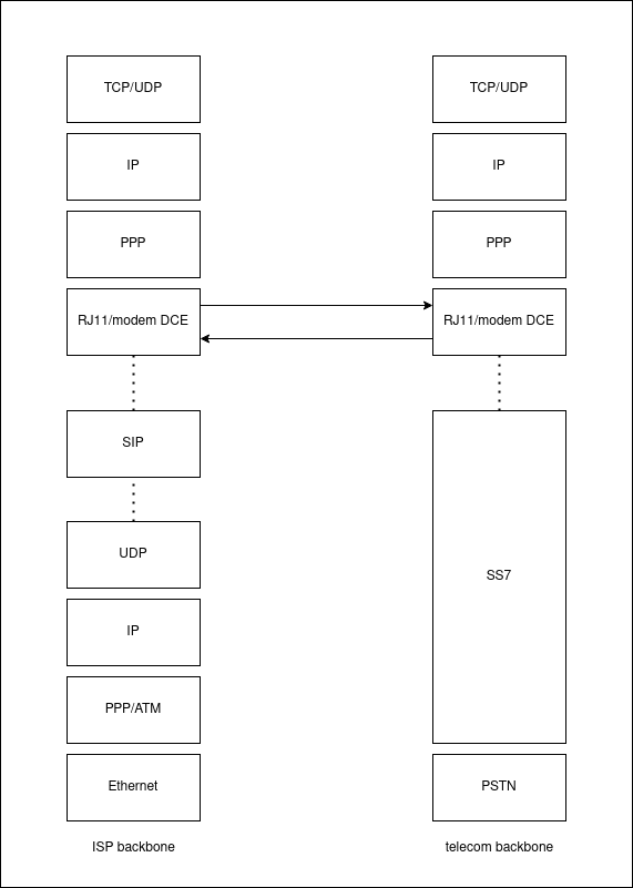 Fig. 3:
Network media stack with ISP and PSTN telecom company backbone model (bottom), and modem-to-modem-established PPP link and further TCP/IP implementation (top).
Fig. 3:
Network media stack with ISP and PSTN telecom company backbone model (bottom), and modem-to-modem-established PPP link and further TCP/IP implementation (top).
hardware and software
In this section, used hardware and software parts are to be described in more detail. Some personal notes/commentaries are present too. Those come from the practical experiences with the devices, and are shown in italics.
modems
- USR 56K Faxmodem (type TBR21 External, ID 24-5631-00, model 5631A) as dial-in server (also as client) modem
- options: V32bis (V.32B), V.80, V.34+, V.90, V.92
- data sheet
Seems to be the most reliable modem series owned (according to tests). Mostly used for testing.
- USR Courier V.Everything 56K Voice Faxmodem (type Czech/Slovakia External) as dial-in server, and client modem
- options: HST, V.32B, V.34+, x2
- data sheet
Modem has troubles making a PPP link (sends gibberish data after the analogue handshake). Electrolytic capacitors have been changed/soldered in, but the troubles are still present.
- USR 56K Voice Faxmodem (type Czech External, model ID 18-5663-00) as client modem
- options: V32bis, V.34+, x2, V.90
Typical USR modem in the CZ/SK region, in my honest opinion. Advertised more than other series/brands. Has to be hard restarted (power off/on) quite often when batch testing. Sometimes it has troubles going off hook after a just-ended dial.
- Microcom DeskPorte Pocket (type Czech External, version 3.02) as client modem
- options: V.90, V.34, V.32bis, MNP5, V.42bis [7]
Tiny blue external modem, reproductors are failable, thus the negotiation(s) are tough to follow. Has a DB9 serial interface as the only modem used.
VoIP gateway
- Well ATA172 plus as VoIP SIP gateway
dial-in server
- Raspberry Pi 4B 8 GB RAM as dial-in server, network access server (NAS)
- Raspbian GNU/Linux 11 (bullseye) as server OS
asterisk(16.28.0~dfsg-0+deb11u1) as NAS software PBXmgetty(1.2.1-1.1) as server modem controllerpppd(version 2.4.9) as PPP link daemon
client
- terminal workstation aka client
- Fedora GNU/Linux 34 as client OS
wvdial(1.61-26) as client dialer softwarescreen(4.08.00 GNU)iperf3(3.9) as link performance evaluation toolwireshark(3.6.2) as frame/packet analysis tool
DTE, DCE and interface transmission speeds
The main system components regarding local loop include [9] [40]:
- DTE – Data Termination (Terminal) Equipment – computer, terminal,
- interface cable [e.g. RS232 (DB25, DB9) modem cable],
- DCE – Data Circuit-terminating (Communication) Equipment – modem + RJ11 cable.
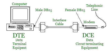 Fig. 4:
DTE and DCE depiction. RS232 plugs being drawn as modem’s model interface cable.
[9]
Fig. 4:
DTE and DCE depiction. RS232 plugs being drawn as modem’s model interface cable.
[9]
In relation to those components mentioned above, two important speeds are present [9] [40]:
- DTE–DCE (DTE, computer–modem) speed – set by
mgetty,wvdialandscreencommands/tools, - DCE–DCE (DCE, modem–modem) speed – to be negotiated between two modems during the dial.
For 56 Kbps bitrate to be achieveable, it is vital for both modem-ends (especially for the dial-in server) to support V.90/V.92 ITU-T recommendations. In case of multiple analogue-to-digital signal conversions in the path of modems, the bitrate defaults to V.34 (33.6 Kbps) or lower speeds. On poor line quality, “a bad line” experience could be present, resulting in slow DCE–DCE speeds. The serial port speed (DTE speed) has to be equal or higher than the expected maximum bitrate. [1] [10] [11] [12]
Furthermore, it is better to completely disable V.90/V.92 standards for modem calls over VoIP. Enabling T.38 standard for faxing service is also recommended (direct data pass-through) as it should increase the line’s quality. It should be better to carry RTP call stream directly between peers, rather than using RTP proxy over the top. Using G.711 (A-law/mu-law) is preferred as non-compressing VoIP codec. Also, stable and of-very-good-quality internet connection is needed (sensitivity to QoS problem) for the RTP stream integrity. Due to PSTN/GSTN call multiplexing, another analogue-to-digital process is present in the way (may possibly lead to lower speeds). [31] [32] [33] [34]
Note: Speed of 33,6 Kbps is achievable on direct telephone line connection using a nullmodem cable. For modem to dial, one has to disable dial tone recognition/checking by ATX0 (ignore all tones) command. Server’s mgetty.conf has to be reconfigured to use direct yes (direct line, on nullmodem cable, see #server-nas-configuration). Any telephone number can be used for the direct call.
[38]
modem indicators and signal controllers
Common modem’s hardware usually provides an user with a simple LED diode indicators bar describing its operational status. Those indicators are labeled by their meaning as abbreaviations — see Tab. 2. Front diode panel examples can be seen in Figg. 5–8.
Tab. 2: Shortcuts and their meanings (have been read off used faxmodems’ plastic covers).
| indicator | description |
|---|---|
AA | auto answer/answer |
CD | carrier detect |
RD | receive data |
SD | send data |
TR | terminal ready |
CS | clear to send |
ARQ/FAX | error control/FAX |
OH | off hook |
MR/PWR/PW | modem ready (power) |
SYN | synchronous mode |
RS | request to send |
HS | high speed |
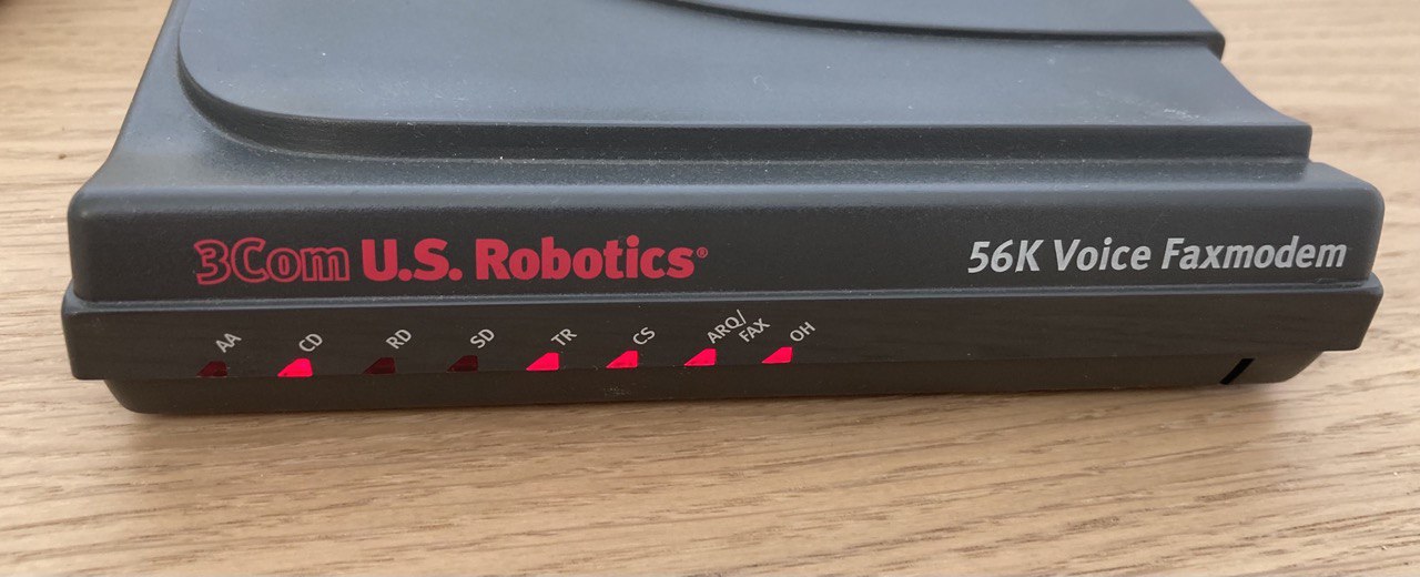 Fig. 5: USR 56K Voice Faxmodem (5663 series) diode indicators (active connection).
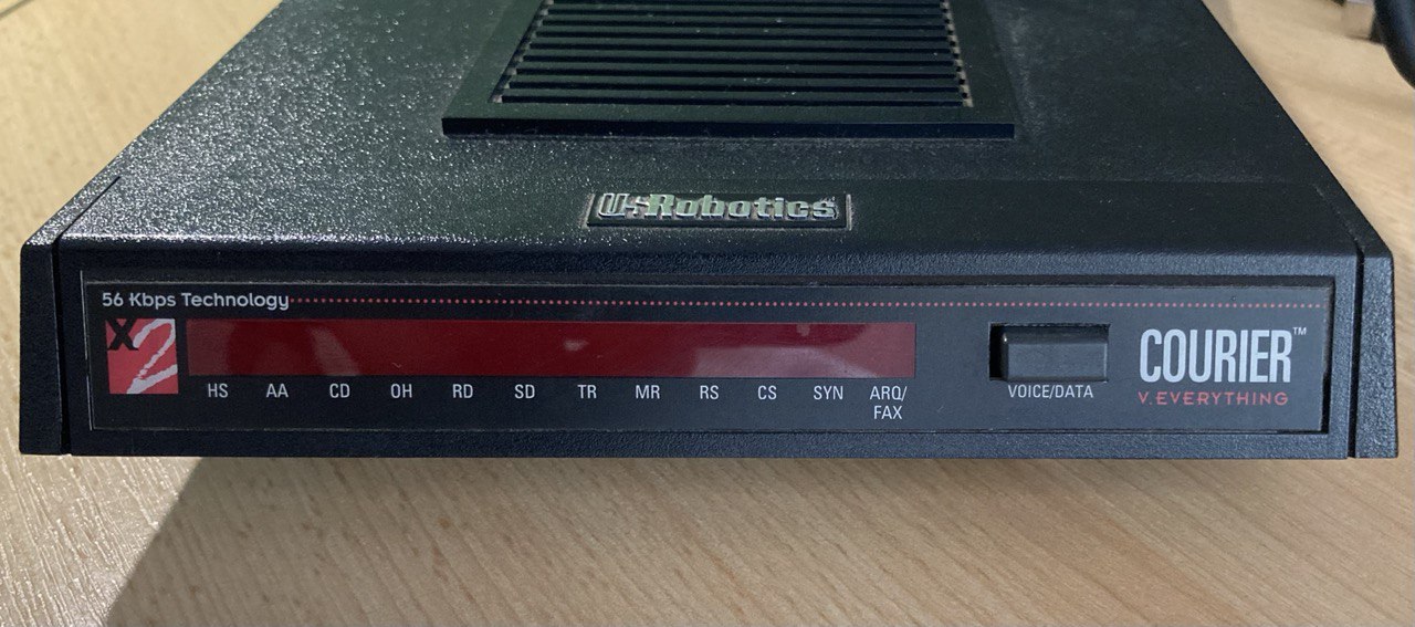 Fig. 6: USR Courier V.Everything front panel with indiators (powered off).
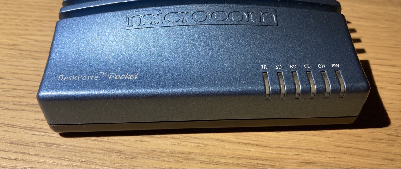 Fig. 7: Microcom DeskPorte Pocket faxmodem (powered off)
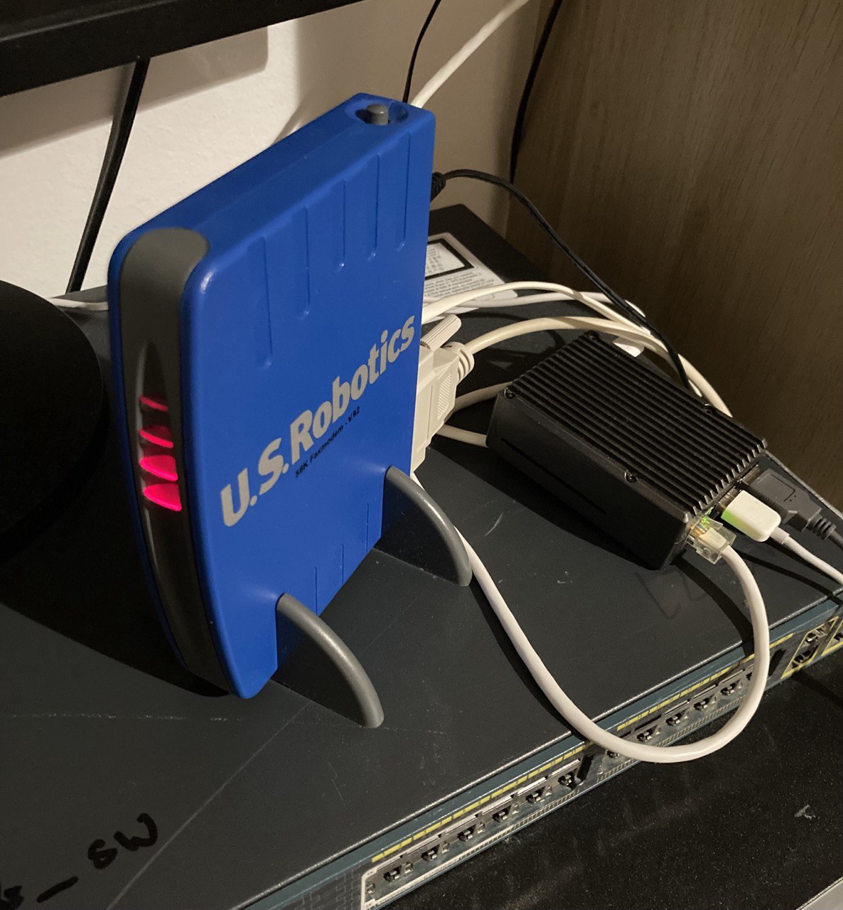 Fig. 8: USR 56K Faxmodem (5631 series) with dial-in Network Access Server (NAS); active connection.
signal controllers
The diode indicators above are controlled by signal(s) being set between the hardware modem, and a terminal computer software equipment. Those signals are usually set by the terminal, thus allowing user to take control over the line and modem’s running configuration. The most used signals are listed in Tab. 3.
Tab. 3: Shortened list of common modem signals carried over the serial line. [6] [13] [41]
| controller | description |
|---|---|
DCD | detect carrier signal |
DSR | data set ready – ready to send data, watch DCD status (&S1 cmd) |
DTR | detect terminal ready signal |
RTS/CTS | hardware flow control (request to send/clear to send) |
EIA232/RS232 pin assignments
All modems used in labolatory are equipped with EIA232/RS232 standard serial port. On the other end, there is a serial-to-USB converting cable. This cable has DB9 (9-pinned serial interface), while most modems carrying DB25 (25-pinned serial interface). This means there must be some other serial-to-serial converting wiring, which is already included by the modem manufacturers in a DB9-to-DB25 serial cable. Table 4 shows, which pins are used by both interface models.
Note: For Tab. 4, Courier’s bottom desk with verbose RS232 pins description has been used one source (transcribed).
Tab. 4: Complete list of DB25’s pins with their according meaning. To be compared with DB9 interface. [40] [41]
| pin index (DB25) | pin index (DB9) | pin description |
|---|---|---|
| 1 | (encloser) | (protective) ground |
| 2 | 3 | transmitted (TX) data |
| 3 | 2 | received (RX) data |
| 4 | 7 | request to send (RTS) |
| 5 | 8 | clear to send (CTS) |
| 6 | 6 | data set ready (DSR) |
| 7 | 5 | singal ground (0 Volts) |
| 8 | 1 | data carrier detect (DCD) |
| 9 | receive clock from DTE (some systems only); test pin | |
| 10 | test pin | |
| 11 | — | |
| 12 | speed indicate; secondary DCD | |
| 13 | secondary CTS | |
| 14 | secondary TX data | |
| 15 | sync TX timing/clock (DCE) | |
| 16 | secondary RX data | |
| 17 | sync RX timing/clock | |
| 18 | — | |
| 19 | secondary RTS | |
| 20 | 4 | data terminal ready (DTR) |
| 21 | signal quality detection | |
| 22 | 9 | ring indicate |
| 23 | signal rate detection | |
| 24 | sync TX timing | |
| 25 | — |
Hayes (AT) command set
AT command set is used to directly communicate with modem’s internal firmware and hardware. Originally, it was introduced by the Hayes company manufacturing earlier modem models, but is used till the contemporal times (e.g. GSM modems implement Hayes command set as well). [13] [14] [15] [16] [30] [43]
USR configuration settings fingerprint using ATI4 command string (ommited command output, to be compared with its meaning):
basic command list
Tab. 5: Incomplete list of common so-called basic (Hayes originally) command set.
| command | cmd value n | description |
|---|---|---|
A | A | force answer mode |
Bn | B0 | auto-adjust DCE-DCE speed to link rate |
En | E0 | no echo |
E1 | echo command characters back to terminal | |
Fn | F1 | |
Hn | H0 | hang-up |
In | I0 | print factory type, product ID |
I1 | print ROM checksum | |
I2 | print intern memory test result (OK or ERROR) | |
I3 | print V.24bis/firmware type and series (revision) | |
I4 | print modem ID, configuration settings | |
I5 | print NVRAM settings | |
I6 | print link diagnostics | |
I7 | print product information | |
Ln | L1 | set modem speakers level to low |
L2 | set modem speakers level to medium | |
Mn | M1 | disable speakers after connect |
P | P | use pulse dialing by default |
Qn | Q0 | set DTR (data terminal ready) signal line |
T | T | use tone dialing by default |
Vn | V1 | verbose responses |
Xn | X0 | ignore all tones (returns only CONNECT) |
X4 | detect dial and busy tone status codes | |
Yn | Y0 | disable disconnect on pause |
Zn | Z0 | reset modem settings to profile 0 (set by &W0) |
extended command list
Tab. 6: Incomplete list of common extended command set. [30]
| command | value n cmd | description |
|---|---|---|
&An | &A3 | protocol result codes |
&Bn | &B1 | fixed serial port rate |
&Cn | &C0 | set DCD control to 1 (don’t watch CD signal) |
&C1 | set DCD control to watch the CD (carrier detect) signal | |
&Dn | &D2 | watch DTR, DTR drop (from 1 to 0) sends hang-up command |
&En | &E0 | disable speed auto-renegotiate according to line quality |
&Fn | &F1 | hardware flow control |
&F2 | software flow control (XON/XOFF) | |
&Gn | &G0 | disable Guard Tone |
&Hn | &H1 | hardware flow control (CTS) |
&In | &I0 | software flow control disabled |
&Kn | &K1 | enable DTE–DCE flow control setting for compression (e.g. V.42bis, MNP 5, NONE) |
&Mn | &M4 | error correction of communication mode, normal/ARQ mode |
&Nn | &N0 | internal time signal source, or link speed selection (highest possible) |
&Rn | &R2 | use hardware flow control (RTS/CTS) setting for received data |
&Sn | &S0 | always set DSR function |
&Tn | &T0 | end test |
&T1 | analog loopback (ALB) | |
&T3 | digital loopback (DLB) | |
&T4 | grant remote DLB | |
&T5 | deny remote DLB | |
&T6 | remote figital loopback | |
&T7 | remote DLB with self test | |
&T8 | ALB with self test | |
&Un | &U0 | variable link rate floor [43] |
&Wn | &W0 | write actual configuration to NVRAM No. 0 |
&Yn | &Y1 | read and load configuration from NVRAM No. 1 |
&Zn=s | write ’s’-number to ’n’-position in NVRAM | |
+F | +FCLASS | faxmodem device mode (0 = data, range 0-255) |
S-registers (shortened)
Tab. 7: List of common (mostly USR-related) S-register list used by USR modems (see #hardware-and-software). To be completed later. [15] [30]
| register number | description | range | default/common value seen from ATI4 command |
|---|---|---|---|
S0 | number of rings before answer (0=never) | 0–255 | 0 |
S1 | ring counter | 0–255 rings | 0 |
S2 | escape character (43 = +) | 0–255 | 43 |
S3 | carriage return character (13 = <CR>) | 0–255 | 13 |
S4 | line feed character (10 = <LF>) | 0–127 | 10 |
S5 | backspace character (8 = <BS>) | 0–127 | 8 |
S6 | wait time before blind dialing | 2–255 seconds | 2, 3 |
S7 | wait for carrier after dial | 1–255 seconds | 50 |
S8 | comma dial delay (pause time) | 0–255 seconds | 2, 3 |
S9 | carrier detect response time | 1–255 tenths of a sec | 6 |
S10 | loss of carrier to hang-up delay | 1–255 tenths of a sec | 14 |
S11 | DTMF tone duration | 50–255 milliseconds | 70 |
S12 | escape code guard time | 0–255 fiftieths of a sec | 50 |
S13 | 0 | ||
S15 | 0 | ||
S16 | bitmap test register | ||
S18 | diagnostic test timer | 0–255 seconds | |
S19 | 0 | ||
S21 | bitmap register | 10 | |
S22 | bitmap register results for tapping speaker volume level | 17 | |
S23 | bitmap register | 19 | |
S25 | delay to DTR | 0–255 seconds/hundreths of a second | 5 |
S27 | bitmap register | 1 | |
S28 | bitmap register for impulse dialing and speed | 8 | |
S29 | 20 | ||
S30 | inactivity disconnect timer (0=disable) | 0–255 tenths of seconds | 0 |
S31 | 128 | ||
S32 | 2 | ||
S33 | 0 | ||
S34 | 0 | ||
S35 | 0 | ||
S36 | 14 | ||
S38 | delay before force disconnect | 0–255 seconds | 0 |
S39 | 12 | ||
S40 | 0 | ||
S41 | 4 | ||
S42 | 0 |
modem standards and modulation protocols
Tab. 8: Selected important modem standards and modulation protocols list, with a short summary, symbol rate and bitrate. [3] [7] [12] [18] [40]
| ITU-T recommendation | description | symbol rate [Bd] | bitrate [bps] |
|---|---|---|---|
| V.22 | — | 600 | 600–1200 |
| V.22bis | — | 600 | 2400 |
| V.24 | aka RS-232 recommendation standard | — | 20000–200000 |
| V.32 | full-duplex on 4-wire and half-duplex on 2-wire circuits – 9.6 or 4.8 kbit/s bidirectional data transfer | 2400 | 9600 |
| V.32bis/V.32B | better modem recommendation allowing up to 14.4 kbit/s bidirctional transfer | 2400 | 14400 |
| V.34 | — | 2400–3429 | 28800 |
| V.90 | — | 3200+ | 56000 |
error correction, and data compression
Tab. 9: Selected ITU-T recommendations for error correction and data compression. [18]
| ITU-T recommendation | description |
|---|---|
| V.42 | error correction protocol, allows immediate corrupted packets retransmission; includes LAPM framing protocol |
| V.42bis/V.42B | adaptive data compression standard |
| V.44 | adaptive data compression, part of V.92 modem standard, allows up to 15% better throughput than V.42bis; usually the compression data rate is about 3:1 (3x speed of pure text transmission) |
CRC (Cyclic Redundancy Check)
CRC detects errors in the data transmission. As the PPP protocol relies on connected nodes to take care of those errors, thus PPP implements CRC. CRC mostly implements checksums as FCS (Frame Check Sequence). Error recovery must be implemented by a different protocol, as the recovery often needs lost/corrupted frames retransmission (ARQ, see below). [3]
ARQ (Automatic Repeat Request)
ARQ is a method using acknowledgements (ACK) for the data transmission. This method is used to ensure reliablity of the transmission data link. [19]
MNP (Microcom Networking Protocol)
Proprietary protocol group by Microcom company, used as recommendations for signal modulation rates (MNP2–MNP4), and for data compression (MNP5). [7]
LAPM/LAPM-SREJ (Link Access Protocol for Modems)
Part of the V.42 error correction protocol. CRC, and ARQ is used for corrupted data retransmission. Frames sent upon LAPM protocol are of a various length, each ending with tail containing CRC information. Received packets are to be ACKed, other packets has to be retransmitted (ARQ). [20]
Special funtionality called Selective Reject (SREJ) allows resending of corrupted packets only to optimize modem-modem speed and for faster error recovery. V.42bis recommendation introduces better compression option, allowing higher throughput for data flow. [20]
modem flow control
Flow control (FC) ensures fluent data transmission from modem to modem. It uses modem’s data buffers for transmitted and received data (congestion control). Flow control operates on those buffers and controls their utilization by stopping and starting data flow. Basically, there is hardware (highly recommended) and software modem flow control. It is very common, that lower ISO/OSI levels utilize hardware FC, while software FC is carried out above those (mostly). [3] [30]
hardware flow control
Hardware FC controls (drops) CTS (clear to send) signal when buffer is about to be filled, and raises it back when buffer is ready (about to be emptied) again. [30]
software flow control
Software FC adds special characters to the data flow to indicate filling buffers. Those special characters are unfortunately part of normal data flow, so it can interfere with software FC special character recognition and therefore can lead to data loss. Those characters are called XON (transmission on) and XOFF (transmission stop), the actual ASCII codes are stored in registers S22 and S23.
[30]
transmission modes
Basically, data can be transmitted using asynchronous and synchronous transmission modes. The core difference is the final connection speed: asynchronous mode is usually way slower, and thus less effective than synchronous mode. [3]
asynchronous mode
In this mode, only one character is transmitted over the link at a time: only one node transmits at any given moment. Usually, the connection bitrate is set up to 1800 bps. Asynchronous modems use Frequency Shift Keying (FSK) modulation for the communication itself. [3] [39]
synchronous mode
This mode introduces whole data blocks transmission as a coherent data flow in both directions (mostly). As far as the modulation is concerned, phase shift keying is very common at bitrates up to 28.8 Kbps. [3] [39]
Synchronous modems are equipped with so-called equalizers, that are used for telephone line quality tuning. Equalizers watch the line attenuation and other telephone signal parameters to optimize their quality compensation effect. [39]
In 4-wire (6P4C) telephone line configuration, one pair can be used for data transmission, while the other for data reception. [2] [39]
point-to-point protocol (PPP) link
PPP is an ISO/OSI layer 2 protocol group — so-called two-point protocol — preceded by SLIP, supports multiprotocol environments [IP/IPX/AppleTalk via NCP (Network Control Protocol)], supports voluntary compression, and periodically checks for link quality and dynamically configures link parameters. [3]
Also, PPP can be used to create link bonds as MP (Multilink PPP), combining multiple serial links/lines to one bonding interface, while adding up to the total interface speed (described as RFC 1990). The (multi)link itself is controlled via LCP (Link Control Protocol) part of the PPP frame. [3]
VoIP parameters
Call data are usually transported using RTP (real-time transport protocol) stream with SIP (session initiation protocol) signaling. [2]
SIP proxy
RTP stream usually flows to-and-from so-called SIP proxy at the VoIP provider’s endpoint. This may add up some latency and delay of the RTP stream itself. SIP proxy acts like SIP signaling router/gateway. As far as the RTP stream is concerned, using SIP proxy (direct RTP stream between peers) might be a better option than implementing B2BUA (back-to-back user agent). [2]
In the Asterisk configuration, a direct media flow is recommended for such setup (sip.conf)
[2]
[4]:
codecs
Tab. 10: Codecs supported by some ISP’s network components list (mainly the VoIP gateway). G.719 is listed due to its fullband characteristics. [2] [3]
| codec name | frequency [kHz] | speed [kbps] | delay [ms] |
|---|---|---|---|
G.711 (g711, alaw, ulaw) | 8 | 56, 64 | 0,125 |
G.719 (g719) | 48 | 32–128 | 40 |
G.722 (g722) | 16 | 48, 56, 64 | 3 |
G.723.1 (g723) | 8 | 5,3; 6,3 | 37,5 |
G.726 (g726) | 8 | 16, 24, 32, 40 | 0,125 |
G.729 (g729) | 8 | 8 | 15 |
Note: no handshake has been completed when using g729 codec (in testing).
packetization
Sending an analogue signal through the IP network requires its packetization. Usually, packetization is defined as milisecond per packet, ms/pkt. Default packetization is 20 ms/pkt for G.711 (used VoIP gateway offers range of 10 to 90 ms/pkt, sometimes even up to 120 ms/pkt). [8] [28] [35] [36]
Note: Tuning packetization value up may link to the overall stream delay — lower packetization leads to lower ICMP RTT on the other hand.
Packetization of 10 ms/packet could be used for faxes sending (g711 with 10 ms/packet).
[28]
configuration
As already mentioned in the very introduction, the next part deals with the whole lab configuration setup.
server (NAS) configuration
mgetty configuration (/etc/mgetty/mgetty.config) for the specific port
[4]
[33]
[38]:
| |
mgetty issue file (/etc/mgetty.issue):
| |
Explanation of the so-called string ’tokens’ from mgetty manpages
[21]:
To ensure computer-modem connection to be enabled, restart and check the systemd service [4] [33]:
| |
Server MOTD (/etc/motd) contents:
| |
Note: vxn.net and vxn.su domains cannot be accessed from the Internet as those are advertised by an internal authoritative DNS server in vxn.dev infrastructure — VPN access only. Domains cannot be resolved even when connected to the dial-in server via modem, because that traffic is not routed to the intranet networks. Some domain may be available on the Internet, but is not connected to vxn.dev organization, thus has been purchased by someone else (public vs. private DNS).
client configuration
To dial from linux system, the wvdial tool has been used. It has got its own config on how to connect to the dial-in counterpart. It is also possible to use pppclient, that has more potent configuration options (ppp client for debian docs).
[22]
[37]
Example of wvdial configuration file (/etc/wvdial.conf)
[23]:
| |
Baud (DTE–DCE speed) shown above is set to the highest possible serial link speed, as this setting should be the default one. [37].
server modem configuration
| |
| |
In the output above, we can see a serious modem-modem speed fluctuation (e.g. abs({"LAST TX rate"} - {"HIGHEST TX rate"})).
| |
client modem configuration
| |
| |
| |
| |
asterisk PBX configuration
sip.conf
The important rule here (as mentioned in #sip-proxy paragraph) is
| |
allowing both modems to communicate without using SIP proxy. This should theoretically improve connetion speeds and VoIP call parameters in general.
implementation
ansible role
For changes (dial-in server) deployment and for configuration versioning an Ansible role repository was created (to be published soon). Role ensures pppd, mgetty, asterisk and screen tools are present on the repomote system. Next, it configures tty ports for pppd amd mgetty, configures SIP accounts for local asterisk instance, reloads system daemons and configuration settings. Client has to apply changes manually.
Repository usage is even more simplified by using Makefile (GNU make). So one can just edit port settings (as described above), and then deploy to server specified by --limit flag of the ansible-playbook command.
dialing up
To dial the remote conterpart — specified by ’lab’ configuration section above — type:
| |
wvdial output when dialing, redacted:
| |
spectral analysis of modem-modem negotiation procedure
 Fig. 9: Negotiation spectral analysis with annotations (
see original
). [ reference ]
Fig. 9: Negotiation spectral analysis with annotations (
see original
). [ reference ]
Note: EMSI_REQA77E string is sent by mgetty server’s daemon, used to negotiate EMSI Request for FIDO.
[24]
PPP routing and DNS resolving issue
Sometimes it is necessary to manually add nameserver for ppp0 network interface and to reset default IP route:
| |
browsing
Using HTTP/S protocols for browsing can clog the connection, so it is better to use simpler protocols like gopher and text-based browsers.
| |
link and data analysis
wvdial handshake readings analysis
Sample connection handshake(s):
| |
Text output (the very first 3 lines) analysis using chapters above. Another handshake(s) examples are to show possible link speed differences (to be discussed further).
First line
- client modem CONNECT response
- modem-modem connection speed
- use ARQ error correction
- use V.32/V.32bis modulation
- use LAPM/LAPM-SREJ protocol
- use V.42bis data compression.
Second line
- wvdial program debug message
- carrier signal ready
- check for PPP link negotiation initialization.
Third line
- no CLIP (caller ID) sent by client
- server tty name used
- NAS-modem (DTE–DCE connection) link speed
- (in parentheses) remote modem’s connection string (set by
mgetty).
iperf link performance
The client-server constallation respects modem-modem connection relation.
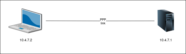 Fig. x: Connection between client and server with corresponding IP addresses. CIDR for the network is /30.
Handshake and carrier details:
server side settings
At first, it is mandatory to setup the server side, namely firewall. Then it is possible to start the iperf tool in server mode.
| |
UDP stream
Down below, there is a sample 10s measurement of the UDP bitrate (should be much longer).
| |
TCP stream
Next, there is a sample TCP server-side output of iperf. The bitrate here should be understood as the rate of received bytes from the client side. Therefore this value should be more exact in terms of the link speed measurement.
| |
Therefore one could say. that the link fluctuated a lot, tuning the link speed negotiated by modems. The bitrate is close to 2400 modem bitrate. [45]
client side
On the client side though, it is not needed to configure anything. Just open the client side end to establish a connection to the remote machine (server).
Down below, sample UDP, and TCP stats are listed.
| |
| |
These TCP bitrates on average are quite low, meaning the connection was very poor.
modem diagnostics
Naks and BLERs
Naks are not-acknowledgments meninging the remoze modem did not confirmed (ACKed) some of set data. BLERs are BLock ERrors — meaning some frames had to be resent. [44]
diagnostics
Dial existing number for data link (make a handshake).
Let us now compare this trimmed output (above) after wvdial executed.
After any call attach screen to just used modem: [25]
| |
U.S. Robotics connection stats (ATI6)
Both connections/calls in the following tho outputs were tested with iperf TCP mode on.
| |
From the output above we could get an average link throughput \(R_{thru}\) and bitrate \(R_{bitrate}\):
$$ N_{chars} = 15,998,842~\text{chars}\\ T_{call} = 10,345~\text{seconds} $$
$$ R_{thru} = \frac{N_{chars}}{T_{call}} \approx 1,546.53~\text{bytes/second} $$
$$ R_{birate} = R_{thru} * 8 \approx 12,372.23~\text{bits/second} $$
This bitrate/throughput is around 86% of the link speed (in the output as “Speed” bitrate).
| |
Again, from the output above we could get an average link throughput \(R_{thru}\) and bitrate \(R_{bitrate}\):
$$ N_{chars} = 151,240,108~\text{chars}\\ T_{call} = 49,796~\text{seconds} $$
$$ R_{thru} = \frac{N_{chars}}{T_{call}} \approx 3,037.19~\text{bytes/second} $$
$$ R_{birate} = R_{thru} * 8 \approx 24,297.55~\text{bits/second} $$
This througput/bitrate is around 84% of the link speed (in the output as “Speed” bitrate).
U.S. Robotics connection stats (ATI11)
| |
Microcom DeskPorte Pocket
| |
frequent disconnection reasons
Next, there are some sample error codes from ATI6 AT command diagnostics.
| |
The explanation No Reversal Detected code is that modem is not receiving any signal reversals – those are vital for phase modulation. [26]
| |
USR Faxmodem series 5663 has troubles with carrier detection pretty often.
Note: To reproduce the one above:
- packetization {20, 30} ms,
- jitter buffer 32 pcts,
- codec alaw,
- EC enabled,
- VAD enabled,
wvdial’s ‘Baud = 57600’
| |
The remote counterpart (NAS) hangs up the connection. Also, user line disconnection using CTRL-C in terminal with wvdial session up. DTR signal can be easily dropped by serial cable physical disconnection.
| |
GSTN stands for General Switched Telephone Network. The background of this phoenomena is not quite understood yet; seen both on remote (odorik.cz) SIP provider loop, as well on local Asterisk PBX loop while testing. [27]
This error should carry a message that the other side dropped the DTR signal, or the disc frame was corrupted. Thi phoenomenta can be seen on non-error correcting connections. [44]
link medium debugging
Note: Statistical test idea: compare dial-up connection/handshake on 10-ms and 20-ms signal packetization (10 means less loss and prolly less noise too).
[28]
Problems getting the handshake over 10-ms packetization setting.
Tab. 11: ATA VoIP gateway settings, with VAD being Voice Activity Detection (VAD) and EC being Echo Cancellation (EC). [2] [29]
Silence supression (VAD being enabled) can disrupt the carrier signal.
provider call stats
Odorik.cz in-network call trimmed log (translated) and statistics (stats).
Tab. 12: Sample VoIP call statistics provided by Odorik.cz SIP ISP (translated).
| |
provider call length limit
SIP ISP may cancel the circuit carrier link after 180 minutes.
Tab. 13: 180-minute VoIP call stats via Odorik.cz SIP ISP (translated, outgoing call).
| |
Tab. 14: 180-minute VoIP call stats via Odorik.cz SIP ISP (translated, incoming call).
| |
link handshake
modem-side call diagnostics
| |
server-side mgetty verbose output
/var/log/mgetty/mg_ttyUSB0.log
| |
VoIP gateway log
The hardware (ATA SIP gateway) needs to be restarted/rebooted quite often to work in more stable way.
Tab. 15: ATA gateway status log, trimmed.
| |
discussion
Nothing interesting or weird found in logs above. May lead to conclusion, that the carrier medium is stable in terms of SIP and RTP stream. Or, those 401 messages (impulses, flap) could lead to the carrier signal to be lost.
A possible solution could be an increase in jitter buffer packet count on the VoIP gateway.
batch connection testing
A special batch heuristic testing of modem-modem connection to fetch various performance variables, statistics. For packet transmission metrics acquirance, a program called wireshark is used, meanwhile iperf3 link performance tests are to be executed (UDP and TCP streams + ICMP stats).
Testing methodology is based on heuristic modem-,link-,medium-variable tuning. Different hardware is tested too (against fixed USR5631 server modem, mostly). Tests are performed on:
- the actual SIP provider’s network (odorik.cz) with RTP proxy,
- local Asterisk SIP PBX with direct data (RTP stream) pass-through between peers.
For both configurations, Well ATA172 is used as SIP gateway. Scraped data are stored in digitalized spreadsheet, with just-changed parameters emphazing (to see testing-time changes).
scraped variables
- dialing modem
- DTE (DTE–DCE) speed [Bd]
- DCE-DCE speed [kbit/s]
- Error Correction (EC)
- modulation and Baud speed [Bd]
- EC protocol
- Data Compression (DC)
- Hardware flow control
- answering modem
- DTE (DTE–DCE) speed [Bd]
- DCE-DCE speed [kbit/s]
- Error Correction (EC)
- modulation and Baud speed [Bd]
- EC protocol
- Data Compression (DC)
- hardware flow control
- VoIP gateway
- packetization [ms/pkt]
- SIP codecs
- silence supression (VAD)
- Echo Cancellation (EC)
- jitter buffer [pkt]
- VoIP provider SIP codecs
- iperf3 stats
- UDP upstream speed [kbit/s]
- UDP downstream speed [kbit/s]
- UDP loss rate [%]
- UDP jitter [ms]
- TCP upstream speed [kbit/s]
- TCP downstream speed [kbit/s]
- TCP MSS [bytes]
- wireshark stats
- UDP thoughput [b/s]
- TCP throughput [b/s]
- TCP RTT peak [ms]
- misc
- ICMP time average, seq 50 [ms]
- ICMP loss rate [%]
- Registered Jack 11 cable used (2-wire/4-wire)
- Disconnection Reason
- Dialing/Answering modem series
- Connection Time [min]
- Line Quality (
ATI6to answering modem, USER5631 only) - Retrain Count (Local/Remote)
- Attempts to Connect + gateway restart needed?
- Dialing Setting AT string
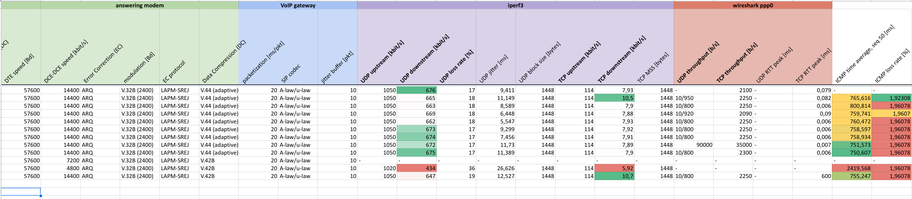 Fig. 10: Cropped spreadsheet thumbnail with speed values heatmapping. (see the screenshot)
testing results
Final statistics:
Tab. 16: Final statistics from remote and local circuit dial-up connection (conn) testing. \(\text{ca}\) stands for circa.
| item name | remote SIP provider circuit | local SIP PBX circuit |
|---|---|---|
| total dial count [-] | \(\underline{678}\) | \(174\) |
| successful handshakes count [-] | \(\text{ca}~103~(15.2~\text{%})\) | \(\underline{\text{ca}~51~(~29.3~\text{%}})\) |
| average attempts to connect count [-] | \(\lceil{}5.60\rceil{} = 6\) | \(\underline{\lceil{}2.81\rceil{} = 3}\) |
| best modulation standard [-] | \(\text{V.}32\text{B}\) | \(\underline{\text{V.34}}\) |
| best compression standard [-] | \(\underline{\text{V.}44}\) | \(\underline{\text{V.44}}\) |
| RTP proxy used [-] | yes | no |
| highest conn bitrate [bps] | \(14400\) | \(\underline{31200}\) |
| average conn bitrate, dialing modem [bps] | \(12567\) | \(\underline{14377}\) |
| longest conn time [minutes] | \(\underline{180^{*}}\) | \(\underline{573.5}\) |
| average conn time [minutes] | \(122\) | \(38.78\) |
| best ICMP RTT [ms] | \(412.96\) | \(\underline{353.73}\) |
| average ICMP RTT [ms] | \(917.45\) | \(\underline{655.35}\) |
| highest TCP downstream bitrate \({R}_{TCP}\) [kbps] | \(12\) | \(\underline{26.6}\) |
| average TCP downstream bitrate \(\overline{R}_{TCP}\) [kbps] | \(7.67\) | \(\underline{8.26}\) |
| highest UDP downstream bitrate \({R}_{UDP}\) [kbps] | \(719\) | \(\underline{850}\) |
| average UDP downstream bitrate \(\overline{R}_{UDP}\) [kbps] | \(588.53\) | \(\underline{645.23}\) |
| best UDP loss rate [%] | \(\underline{0.52}\) | \(4.6\) |
| average UDP loss rate [%] | \(21.51\) | \(\underline{17.18}\) |
| best UDP jitter [ms] | \(\underline{3.182}\) | \(3.55\) |
| average UDP jitter [ms] | \(17.00\) | \(\underline{15.02}\) |
| points (underlined values) [-] | \(5/20\) | \(15/20\) |
\(^{*}\)Remote SIP provider limits the connection time (call duration) to 180 minutes.
discussion and conclusion
During the testing part, more than 840 calls had been executed to establish a dial-up handshake. On average, it took 6 and 3 attempts to get a handshake — to establish a successful connection for remote and local circuits respectively.
Comparion of Tab. 16 shows that local SIP circuit gives better results than when remote SIP provider’s circuit used. This could lead to a conclusion that bypassing SIP proxy is important for modem’s sensitive information exchange during the negotiation phase and thus leads to a better call quality.
connection speeds
- Why is the UDP downstream bitrate 70–80 times the TCP downstream bitrate? How can the UDP downstream speed be higher than the connection bitrate?
The main difference between UDP and TCP connection speeds are that UDP tests are provided using a continuous datagram stream from client to server, while TCP requires 3-way handshakes to reliably send packets.
The reliability of UDP stream can be qualified by the UDP loss rate, which is quite high for both circuits (above 15 %).
The other important part here is software/hardware flow control in action on both modems. It is not quite known now (to be further inspected), if both modems are in sync with the flow control. According to the configuration of both modems, software flow control should be disabled (mostly by default) as it could lead to data loss via its control characters used for the flow control itself.
Let \(R_{UDP}\) be the average UDP downstream bitrate, let \(L_{UDP}\) be the average UDP loss rate, and let \(R_{clr}\) be a cleared UDP bitrate from lost traffic. Then:
$$R_{clr} = R_{UDP} \times (1 - L_{UDP})~[\text{kbps}]$$
For both remote and local circuits respectively then:
$$R_{clr} = 588.53 \times (1 - 0.2151) \land R_{clr} = 645.23 \times (1 - 0.1718)$$ $$R_{clr} = 461.94~\text{kbps} \land R_{clr} = 534.38~\text{kbps}$$
Even when cleared by loss rate, the bitrate is still quite high (way above average connection bitrate). It is also important to consider, that average values are biased by extremes (extreme top and bottom values). However, this problem should be minimized by the batch size (678 and 174 callings for remote and local circuit respectively).
Errors could also possibly be in the used iperf default settings — TCP window being disabled in sysctl [42]:
| |
Moreover, it has been discovered, that the methodic of iperf usage for link speed testing was not used properly. See the next chapter of the new testing round.
link revision (Jan 2024)
Tab. x: Selected parameters and configurations of modems and ATA.
| property name | property value |
|---|---|
| packetization [ms/pkt] | 10 |
| jitter buffer [pkt] | 3 |
| SIP codec | G.711 Alaw |
| VAD | no |
| echo cancellation | no |
second test round
references
printed
| reference index | issue/book/bulletin name |
|---|---|
| [1] | 56K Faxmodem, Quick Installation Guide. U.S.Robotics, revision 4 11/05, 2004. https://support.usr.com/support/5631a/5631a-files/5631a-multi-ig.pdf |
| [2] | ŠILHAVÝ, Pavel. Telekomunikační a informační systémy. Brno: Vysoké učení technické v Brně, 2014. s. 1-140. ISBN: 978-80-214-5027-1. (CZ) |
| [3] | PUŽMANOVÁ, Rita. TCP/IP v kostce. 2., upr. a rozš. vyd. České Budějovice: Kopp, 2009. ISBN 978-80-7232-388-3 (CZ). |
online
Cited using scribbr.com.
further telco lab ideas
- xDSL service
- LoRa P2P link